ASK SENSEI
.net
AN E-LEARNING TOOL BUILT JUST FOR YOU
Whiteboard
SAT® Vocab Practice
Tutorial
About
Contact
Math Studio
Whiteboard
SAT® Vocab Practice
Tutorial
About
Contact
Math Studio
Log in
What is force diagram and how to draw it
• Physics •
AP Physics
Mechanics
Statics
## What is a Force Diagram? A **force diagram**, commonly referred to as a **Free-Body Diagram (FBD)**, is the single most important visual tool in classical mechanics. It is a schematic representation used to isolate a single object and show all the real, physical forces acting *on* that object at a specific moment in time. 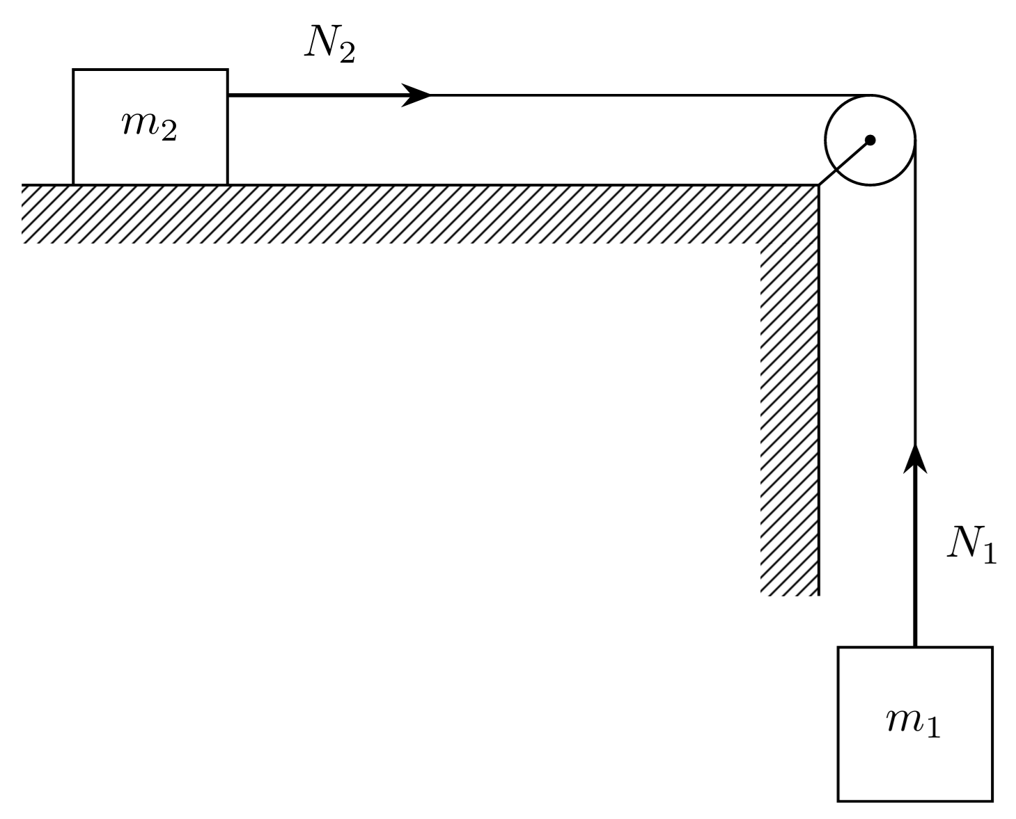 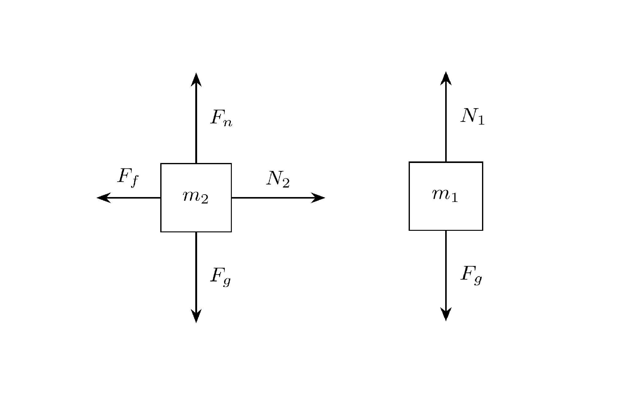 In AP Physics, an accurate FBD translates directly into correct vector components, allowing you to successfully apply Newton's Second Law ($\sum \vec{F} = m\vec{a}$) and solve complex kinematics and dynamics problems. --- ## Step-by-Step Guide to Drawing a Free-Body Diagram To construct a rigorous FBD that earns full credit on AP exams, follow this systematic six-step procedure: ### 1. Isolate the System * **Rule:** Choose one specific object of interest and mentally (or physically) cut away everything else in the environment touching it. * **Tip:** Never include forces exerted *by* the object on other things; only include forces exerted *on* your chosen object by its environment. ### 2. Represent the Object as a Point Particle * **Rule:** Unless you are analyzing rotational torque problems (where object geometry and pivot points matter), draw the object as a simple dot or a small box at the origin of a coordinate system. Treating it as a point particle keeps vector tails aligned at a single origin. ### 3. Identify and Draw Field Forces (Long-Range Forces) * **Rule:** Start with forces that do not require physical contact. * **Weight/Gravity ($F_g$ or $W$):** Always draw a vector pointing straight down toward the center of the Earth, calculated as $mg$. ### 4. Identify and Draw Contact Forces * Scan the perimeter of your isolated object wherever it touches another surface, string, fluid, or field. Look for: * **Normal Force ($F_N$):** Perpendicular to the surface of contact, pushing *away* from the surface. * **Friction ($f_s$ or $f_k$):** Parallel to the contact surface, opposing relative motion or intended motion. * **Tension ($T$):** Pulling along the direction of a taut rope, string, or cable *away* from the object. * **Applied Forces ($F_{app}$):** Pushes or pulls exerted by external agents (e.g., a hand pushing a box). ### 5. Establish a Convenient Coordinate System * **Rule:** Draw standard $x$ and $y$ axes intersecting at the dot. * **Incline Pro-Tip:** For inclined planes or systems moving along a ramp, **tilt your coordinate system** so that the $x$-axis runs parallel to the ramp surface and the $y$-axis runs perpendicular to it. This minimizes the number of vectors you have to split into components (you only have to decompose gravity, $F_g$). ### 6. Verify Vector Proportions and Labels * **Relative Lengths:** If the object is accelerating in a specific direction, the forces in that direction should visually reflect a net force (e.g., if a box accelerates to the right, make your rightward force vector longer than your leftward friction vector). If the object is in equilibrium ($\sum F = 0$), opposing vectors must look equal in length. * **Standard Variable Labels:** Use clear subscripts (e.g., $F_g$, $F_N$, $f_k$, $T$) rather than ambiguous numbers. --- ## Common Forces Checklist | Force Name | Symbol | Direction | Typical Magnitude Equation | | --- | --- | --- | --- | | **Weight (Gravity)** | $F_g$ (or $W$) | Directly downward | $mg$ | | **Normal Force** | $F_N$ | Perpendicular to contact surface, outward | Equal to perpendicular component of net other forces (variable) | | **Static Friction** | $f_s$ | Parallel to surface, opposing *intended* motion | $f_s \le \mu_s F_N$ | | **Kinetics Friction** | $f_k$ | Parallel to surface, opposing *actual* motion | $f_k = \mu_k F_N$ | | **Tension** | $T$ | Along the rope, pulling away from the object | Dependent on system acceleration | --- ## Example: Box Sliding Down a Rough Incline Imagine a block of mass $m$ sliding down an inclined plane at an angle $\theta$ with friction. Here is how the FBD is structured: 1. **Dot:** Place a dot at the center of your axes. 2. **Tilt Axes:** The $x$-axis points down-slope; the $y$-axis points straight up off the ramp surface. 3. **Gravity ($F_g$):** Points straight down vertically (straight down on your page, *not* perpendicular to the tilted axes). Break $F_g$ into components: $mg \sin(\theta)$ down the slope (along $-x$) and $mg \cos(\theta)$ into the ramp (along $-y$). 4. **Normal Force ($F_N$):** Points straight up along the positive $y$-axis, balancing $mg \cos(\theta)$. 5. **Friction ($f_k$):** Points up the slope along the positive $x$-axis, opposing the downward slide. --- ## Immediate Execution Steps * **Component Breakdown:** Once your FBD is sketched, immediately write out your component summations: $\sum F_x = ma_x$ and $\sum F_y = ma_y$ (or $0$ if equilibrium). * **Substitution:** Substitute the specific force expressions ($mg \sin\theta$, $\mu_k F_N$, etc.) directly into your component equations before plugging in any numerical values.